Kinect v2 – Kinect xbox one on ROS noetic – ubuntu 20.04 – Cuda 10.1

Exploring Kinect v2 – Kinect xbox one on ROS noetic – ubuntu 20.04 – Cuda 10.1

Software required, cuda its optional

cuda 10.1

libfreenect2

iai-kinect2


https://www.notaboutmy.life/posts/run-kinect-2-on-ubuntu-20-lts/

I followed the document available on  address above, to successfully install the cuda and libfreenect2 with cuda.

As is, the procedure described failed. I need  to add some more steps. The steps are found after hours of trial and error.

This process install the cuda 10.1 from the ubuntu 20.04 repos. Before this procedure I tried the installation form nvidia repos, but i never had success.

Install and test nvidia cuda from ubuntu repos

apt-get install cuda-toolkit -y

After install you may check the installed cuda compiler version with

nvcc –version
nvcc: NVIDIA (R) Cuda compiler driver
Copyright (c) 2005-2019 NVIDIA Corporation
Built on Sun_Jul_28_19:07:16_PDT_2019
Cuda compilation tools, release 10.1, V10.1.243

Then to check if the cuda is working, you need to compile the hello.cu code available in the following address:

https://linuxconfig.org/how-to-install-cuda-on-ubuntu-20-04-focal-fossa-linux

Compile a Sample CUDA code

$ nvcc -o hello hello.cu
$ ./hello
Max error: 0.000000

The result must be

Max error: 0.000000

if we get the following, something is wrong

Max error: 2.000000

You can proceed with libfreenect2 installation, but cuda will not work


Prepare the install of libfreenect2, installing the build tools and libraries

sudo apt-get install build-essential cmake pkg-config
sudo apt-get install libusb-1.0-0-dev
sudo apt-get install libturbojpeg0-dev
sudo apt-get install libglfw3-dev
sudo apt-get install libva-dev libjpeg-dev
sudo apt-get install libopenni2-dev
sudo apt-get install doxygen
sudo apt-get install nvidia-opencl-dev

You need gcc 8 to compile libfreenect2 with cuda

sudo apt -y install gcc-7 g++-7 gcc-8 g++-8 gcc-9 g++-9
sudo update-alternatives –install /usr/bin/gcc gcc /usr/bin/gcc-7 7
sudo update-alternatives –install /usr/bin/g++ g++ /usr/bin/g++-7 7
sudo update-alternatives –install /usr/bin/gcc gcc /usr/bin/gcc-8 8
sudo update-alternatives –install /usr/bin/g++ g++ /usr/bin/g++-8 8
sudo update-alternatives –install /usr/bin/gcc gcc /usr/bin/gcc-9 9
sudo update-alternatives –install /usr/bin/g++ g++ /usr/bin/g++-9 9

# select v8:

sudo update-alternatives –config gcc
sudo update-alternatives –config g++

# check version

gcc –version
g++ –version
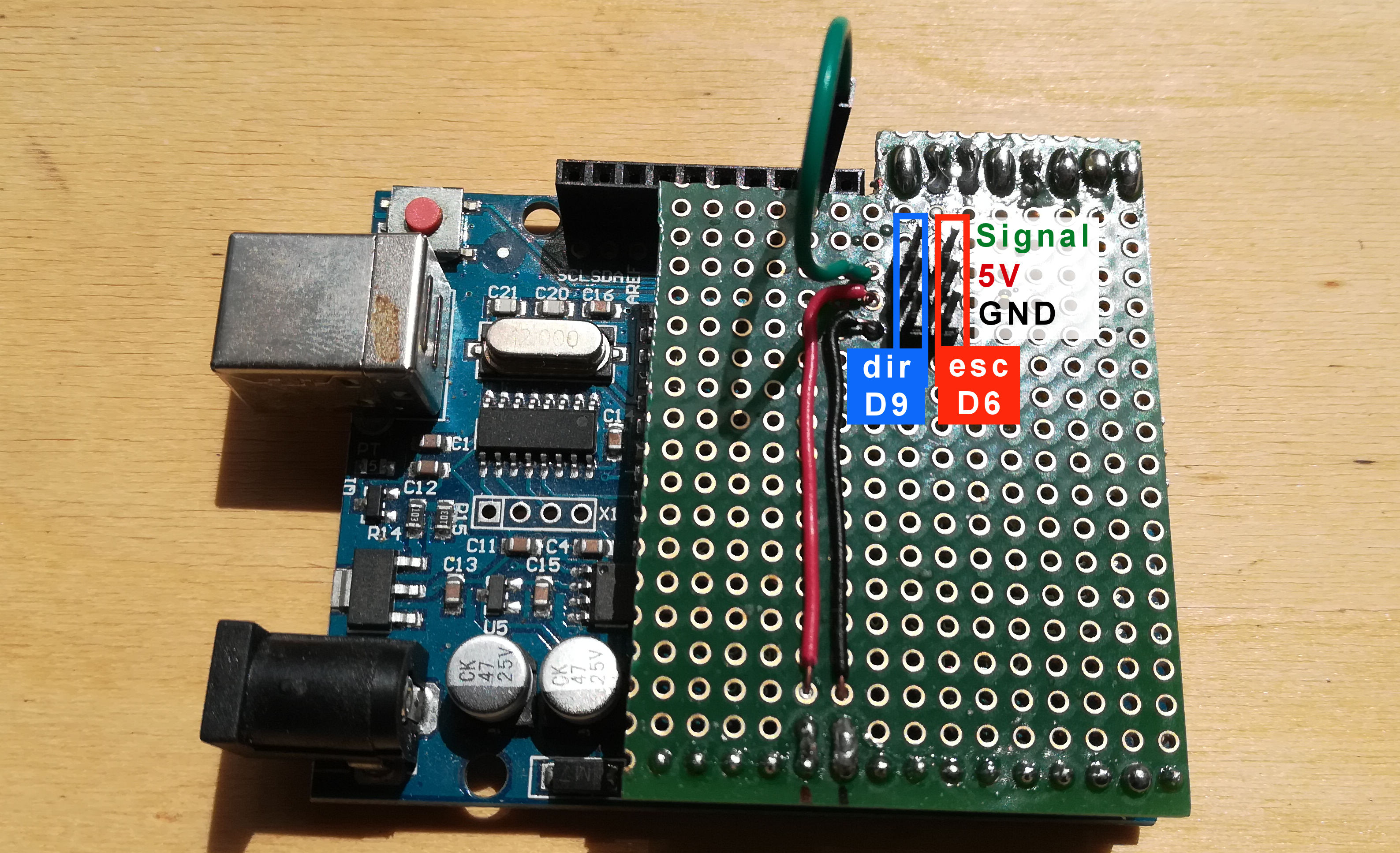


Traxxas Arduino Shield

O Traxxas Arduino Shield foi feito para substituir a placa branca aplicada no robot. É muito simples pois o único objetivo foi eliminar a placa branca e a maior parte dos fios existentes.

O shield encaixa em parte dos headers do Arduino Uno e permite encaixar os fios de ligação do esc dos motores e do servo da direção nuns conectores de 3 pinos.

A forma de ligar o esc e o servo ao shield está ilustrada na imagem. É de notar que se bem que o sinal do conector destinado ao esc está sempre ligado ao pino D6 do arduino, o sinal do conector destinado ao servo, tem de ser ligado, com o fio verde, ao pino D9.

O shield tem espaço para possíveis desenvolvimentos, entre os quais a colocação de um condensador na alimentação (GND e 5V)

A imagem indica claramente as ligações a efectuar.

micropython-rosserial scripts and ros

The following command must be executed in the computer with the rosmaster.

rosrun rosserial_arduino serial_node.py _port:=/dev/ttyUSB0 _baud:=115200

The baud must match the baud in the uros.NodeHandle statement in the micropython-rosserial script.

micropython-rosserial publisher sample code


import uros
from std_msgs import ColorRGBA #message object ColorRGBA
from time import sleep
node=uros.NodeHandle(2,115200) #node initialized, for tx2/rx2 and 115200 baudrate
msg=ColorRGBA() #msg object init
msg.r=1 #values to variables assigned
msg.g=3
msg.b=4
msg.a=1
while True:
    node.publish('Colorsh',msg) #publish data to node Colorsh
    sleep(1)


micropython-rosserial subscriber sample code

import uros
from std_msgs import String

def cb(msg):
	print(msg.data)
	
node = uros.NodeHandle(2, 115200)
node.subscribe('chatter', String, cb)


micropython-rosserial subscriber and publisher sample code


import uros
from std_msgs import String

def cb(msg):
	print(msg.data)
	
packet=String()
packet.data='hola fpy'
node = uros.NodeHandle(2, 115200)
node.subscribe('chatter', String, cb)
while True:
	node.publish('greet', packet)


Node constructor

uros.NodeHandle(SERIAL_ID = 2, BAUDRATE = 115200, **KWARGS)

Remark: there are 3 serial ports in esp32

**KWARGS are arguments for a custom serial port connection.

More info about micropython-rosserial

https://pypi.org/project/micropython-rosserial/

end

micropython-rosserial create required ROS message classes from msg files

As stated in micropython-rosserial documentation, any ROS message type to be used by a node must be created  before they can be used in micropython-rosserial based scripts.

The message class files are generated by module ugenpy, one of the additional modules installed during the pip install of the micropython-rosserial.

But although the module is installed it doesn’t install the folder of with the message definition files, the *.msg files, for the std_messages.

So we need to copy the msg definition files to our MicroPython device.

Before we can do that we need:

  • the .msg files for ROS std_msgs;
  • the software to copy then to the file system of our MicroPython device;

Lets do it now.

Get the std_msgs .msgs files from github

github repository to the /std_msgs folder in our MicroPython device.

cd ~/
git clone https://github.com/FunPythonEC/uPy-genpy
cd uPy-genpy/src

Install rshell

The rshell is the software to copy the files to (and from) the microPython file system.

It can also be used as serial terminal to access the microPython console (the REPL)

sudo pip3 install rshell

After installation we can run it with the following command

rshell connect serial /dev/ttyUSB0 115200

We get automatically connected to our micropython device.

We may also just run rshell and issue the connect insider the rshell.

The command help give the available commands.

help

Documented commands (type help <topic>):
========================================
args cat connect date edit filesize help mkdir rm shell
boards cd cp echo exit filetype ls repl rsync

The boards command give the avalilable / connected boards.

boards

pyboard @ /dev/ttyUSB0 connected Epoch: 2000 Dirs: /boot.py /lib /main.py /project.pymakr /rospub.py /rossub.py /utils.py /pyboard/boot.py /pyboard/lib /pyboard/main.py /pyboard/project.pymakr /pyboard/rospub.py /pyboard/rossub.py /pyboard/utils.py

The repl command gives us access to the microphython console, the REPL.

repl

Entering REPL. Use Control-X to exit.
>
MicroPython v1.15 on 2021-04-18; ESP32 module with ESP32
Type "help()" for more information.
>>>

Our micropython device file system is available under the following path:

/pyboard

So we in order to copy our folder std_msgs from our computer to our micropython file system, we use the following command

cp -r std_msgs /pyboard

After some seconds all the files are copied and you could list the /std_msgs folder in the file system of our micropython device with:

ls /pyboard/std_msgs

Bool.msg Duration.msg Float64MultiArray.msg Int32MultiArray.msg MultiArrayDimension.msg UInt16MultiArray.msg UInt8.msg 
Byte.msg Empty.msg Header.msg Int64.msg MultiArrayLayout.msg UInt32.msg UInt8MultiArray.msg 
ByteMultiArray.msg Float32.msg Int16.msg Int64MultiArray.msg String.msg UInt32MultiArray.msg 
Char.msg Float32MultiArray.msg Int16MultiArray.msg Int8.msg Time.msg UInt64.msg 
ColorRGBA.msg Float64.msg Int32.msg Int8MultiArray.msg UInt16.msg UInt64MultiArray.msg

I just copy all the messages, but, in order to spare space, we should only copy the required ones.

Now that we have the msg files in our micropython device, we may start to create de ROS message class files required for our test scripts.

Go to the REPL (micropython console) with the following command.

repl

And enter the following lines on the REPL

from ugenpy.message import MessageGenerator

msg=MessageGenerator('std_msgs/ColorRGBA.msg')
msg.create_message()

msg=MessageGenerator('std_msgs/String.msg')
msg.create_message()

The first part import the required module

The second part, create the py class file for the file ColorRGBA.msg

The third part, create the py class file for the file String.msg

We get some info about the processed data types. For the first file is:

data type processed: float32 to be <f

For the second file, we get:

data type processed: string to be <I%ss

We may check if the files exist inside the REPL, with the following commands.

> import os
>>> os.listdir('std_msgs')
['Bool.msg', 'Byte.msg', 'ByteMultiArray.msg', 'Char.msg', 
(...)
 'UInt8MultiArray.msg', '_ColorRGBA.py', '_String.py', '__init__.py']


https://pypi.org/project/micropython-rosserial/

https://github.com/FunPythonEC/uPy-genpy

micropython-rosserial install on ESP32-CAM

Install micropython-rosserial on ESP32-CAM it is very easy.

The easy way is install it with upip. It requires internet access. So before we install the micropython-rosserial on ESP32-CAM, we need to connect it to the internet.

The full procedure is this one:

1 – Connect the computer to the ESP32-CAM via the FTDI USB-Serial interface.

2 – Access to the MicroPython console with a terminal software, or with the pyMakr vscode extension.

3 – Connect to the internet

On MicroPython console input the following commands

import network
wlan = network.WLAN(network.STA_IF)
wlan.active(True)
wlan.connect('ssid', 'password')
wlan.ifconfig()

The last statement only gets the ip config, and show us in the terminal. Ex:

>>> wlan.ifconfig()
('192.168.1.108', '255.255.255.0', '192.168.1.1', '192.168.1.1')

4 – Install the micropython-rosserial module and dependencies

import upip
upip.install('micropython-rosserial')

The success message sample is something like the following one.

Installing to: /lib/
Warning: micropython.org SSL certificate is not validated
Installing micropython-rosserial 0.2.7 from https://files.pythonhosted.org/packages/39/ff/9f04ae38d6245d8c0d63b3c6fa052d87088038c2e12748c811e1196e56e4/micropython-rosserial-0.2.7.tar.gz
Installing micropython-genpy 0.0.6 from https://files.pythonhosted.org/packages/b0/eb/24c691b2cfb95c638da4c95585437b2009fb0baa0a3c8bca0791fdf34188/micropython-genpy-0.0.6.tar.gz
Installing micropython-rosserial-msgs 0.0.1 from https://files.pythonhosted.org/packages/e5/4d/cd3f085dab632d499bc256e0d50c2a180adf2c43ae008efabeaa1a292fa5/micropython-rosserial_msgs-0.0.1.tar.gz
Installing micropython-logging 0.3 from https://micropython.org/pi/logging/logging-0.3.tar.gz
>>>

After we may check the contents of the lib folder

import os
os.listdir('lib')
['logging.py', 'rosserial_msgs', 'ugenpy', 'uros']

The installation is done.

Lets explore it!

Source:


https://pypi.org/project/micropython-rosserial/

ESP32-CAM ROS rosserial_arduino platformio

ESP32-CAM ROS rosserial_arduino platformio

Create a new project, and select:
Board: AI Thinker ESP32-CAM
Framework: Arduino

Add the Rosserial Arduino Library from frankjoshua to the project
lib_deps = frankjoshua/Rosserial Arduino Library@^0.9.1

For a simple demo over wifi copy the sample in the following file

Esp8266HelloWorld.ino
.pio/libdeps/esp32cam/Rosserial Arduino Library/examples/Esp8266HelloWorld

Remove the following line (near line 13)
#include <ESP8266WiFi.h>

//Change the wifi ssid and pass
const char* ssid = “your-ssid”;
const char* password = “your-password”;

// Set the rosserial socket server IP address
IPAddress server(192,168,1,1);

// Check the
const uint16_t serverPort = 11411;

Compile and upload

On the ros master run the rosserial node in tcp mode

rosrun rosserial_python serial_node.py tcp

We can build and install the ros_lib for the current ros version by install the rosserial arduino

sudo apt install ros-noetic-rosserial-arduino

And build the library with the following command

rosrun rosserial_arduino make_libraries.py .

After, we shall copy the ros_lib folder to the lib folder of the platformio project

The last rosserial_arduino version on the following address

https://github.com/ros-drivers/rosserial/

ESP32-CAM Video on ROS

ESP32-CAM on ROS

Install the Micro-RTSP in Platformio (use the add library to a project tool)

https://github.com/geeksville/Micro-RTSP

The github version altough the same number is not the same installed by add library to a project tool, in platformio.

So dont mix the samples or you will get some linking errors.

This error can be the result of a bad powering, or bad board configuration (because there are more than one model of ESP32-CAM)

[E][camera.c:1049] camera_probe(): Detected camera not supported.
[E][camera.c:1249] esp_camera_init(): Camera probe failed with error 0x20004

To fix it, it is a configuration issue, in setup(), try to change

cam.init(esp32cam_config);

to

cam.init(esp32cam_aithinker_config);

or to:

cam.init(esp32cam_ttgo_t_config);


The file folowing file have the configurarion for each model:

.pio/libdeps/esp32can/Micro-RTSP/OV3640.cpp

If we reduce the .frame_size we can make a more fluid video.

Change from

.frame_size = FRAMESIZE_SVGA,

To

.frame_size = FRAMESIZE_QVGA,

Its a good improvement

There are chances of some serial monitor issues,

Check, if  cannot see any output in platformio serial monitor.


Stream URL

rtsp://[IPADDRESS]:8554/mjpeg/1

In VLC choose :network-caching=0 in VLC

There are some issues with performance with ROS compared with VLC

For ESP32-Cam we need the following firmware

https://github.com/inaciose/esp32-cam-rtsp


For ROS we may use the following packages

http://wiki.ros.org/video_stream_opencv

sudo apt install ros-noetic-video-stream-opencv

Or

https://github.com/inaciose/sibot_video

Clone and catkin_make


Serial issue ESP32-CAM – MB – vscode – platformio

If  the serial monitor of platformio in vscode doesnt output anything, maybe its because some ESP32 boards have a mechanism that connects RTS/DTR to the EN/GPIO0 lines, and if the RTS/DTR are driven the wrong way when the serial monitor opens, it might shut down the ESP32.

We can try adding each of follow blocks to the platformio.ini and retry opening the serial monitor, until it works.

If one doesn’t make a difference, delete it and try again withthe next one.

1.)

monitor_rts = 0
monitor_dtr = 0

2.)

monitor_rts = 0
monitor_dtr = 1

3.)

monitor_rts = 1
monitor_dtr = 0

4.)

monitor_rts = 1
monitor_dtr = 1

https://docs.platformio.org/en/latest/projectconf/section_env_monitor.html

For me, with the ESP32-CAM (aithinker clone) with MB (The mother board allow to program directly from usb cable), the one that works was:

monitor_rts = 0
monitor_dtr = 0

platformio.ini file sample for the project

[env:esp32cam]
platform = espressif32
board = esp32cam
framework = arduino
monitor_speed = 115200
lib_deps = geeksville/Micro-RTSP@^0.1.6
monitor_rts = 0
monitor_dtr = 0

There are some usefull comands to check the serial comunications on platformio, the following are a sample;

pio device monitor –encoding hexlify
pio device monitor –filter debug

pio device –help
pio device COMMAND –help

Info source

https://community.platformio.org/t/noob-stuck-on-esp32-cam-mb-with-pio-vscode/19117/4

traxxas_firmware

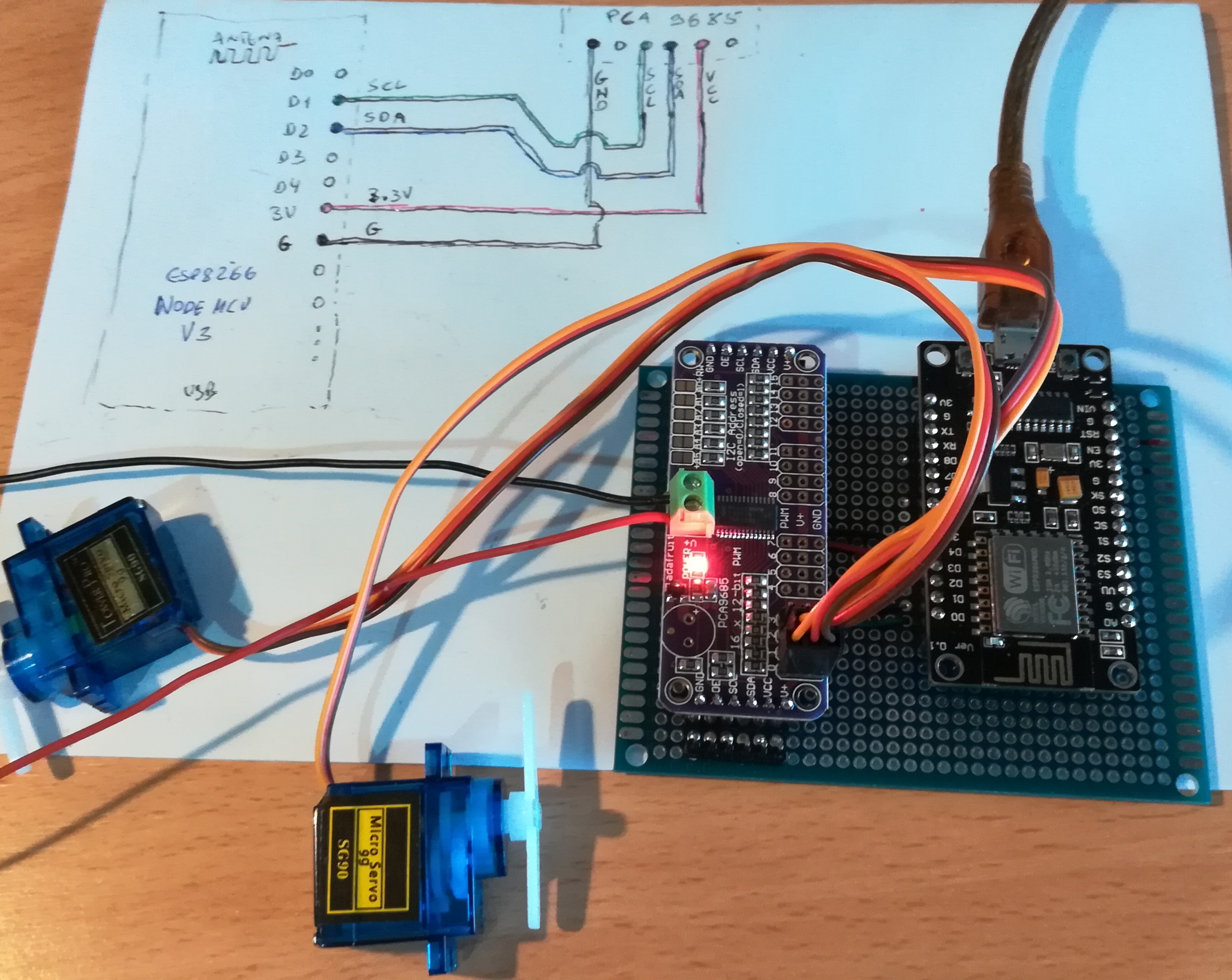
Firmware de controlo com ROS do servo da direcção e do ESC de um rover traxxas, para um  ESP8266 nodeMCU V3 com um PCA9685.

Usado no rover traxxas do Automec – Universidade de Aveiro

O firmware subscreve os tópicos:

  • pub_dir, (angulo de direcção entre -90º e 90º a aplicar ao servo)
  • pub_vel (velocidade expressa entre |0, 90| sendo o seu sinal indicador da direcção, o negativo é marcha atrás)

Pode ser expandido para controlar também o servo do diff. traseiro e do diff. dianteiro.

  • ESP8266 (micontrolador de 32bits com wifi integrado);
  • PCA9685 (gerador de PWM de 12bits e 16canais)


  • IDE: platformIO,
  • Board: ESP8266 nodeMCU 12E

Na primeira fase está implementado o controlo do ESC e do servo da direcção.

A ligação do firmware aos node ROS depende do pacote rosserial.

Caso não esteja instalado, pode-se instalar com o seguinte comando (substituir noetic, pela identificação da distribuição do ROS):

sudo apt install ros-noetic-rosserial

Depende de um node que publique mensagens twist nos tópicos apropriados. Como por exemplo o node: linang_to_ackermann.py.

O node deve ser lançado com a seguinte configuração

message_type:=physical

O node pode ser configurado para dois tipos de input,:

train:=1 (subscreve um único tópico twist com velocidade angular e linear)

train:=0 (pré-definido, subscreve dois tópicos twist, um com velocidade angular, e outro com a velocidade linear)

Identificação da porta serie a usar na comunicação

~$ dmesg
[12722.986709] usbserial: USB Serial support registered for ch341-uart
[12722.986727] ch341 1-1:1.0: ch341-uart converter detected
[12722.987254] usb 1-1: ch341-uart converter now attached to ttyUSB0

Exemplos de exploração do sistema

Cada um dos comandos deve ser lançado num terminal independente

Exemplo de exploração em modo real e autónomo com o node linang_to_ackermann.py (usando um launch file)

rosrun rosserial_python serial_node.py /dev/ttyUSB0
roslaunch ackermann_vehicle_gazebo linang_to_ackermann.launch message_type:=physical

Exemplo de exploração em modo real e treino com o node linang_to_ackermann.py (usando um launch file)

rosrun rosserial_python serial_node.py /dev/ttyUSB0
roslaunch ackermann_vehicle_gazebo linang_to_ackermann.launch message_type:=physical train:=1
rqt


Exemplo do output de uma ligação bem sucedida do node serial_node.py

~$ rosrun rosserial_python serial_node.py /dev/ttyUSB0
[INFO] [1620470781.458011]: ROS Serial Python Node
[INFO] [1620470781.460781]: Connecting to /dev/ttyUSB0 at 57600 baud
[INFO] [1620470783.566170]: Requesting topics...
[INFO] [1620470783.599243]: Note: subscribe buffer size is 512 bytes
[INFO] [1620470783.603585]: Setup subscriber on pub_dir [std_msgs/Int16]
[INFO] [1620470783.618133]: Setup subscriber on pub_vel [std_msgs/Int16]
^C[INFO] [1620470867.461564]: Sending tx stop request


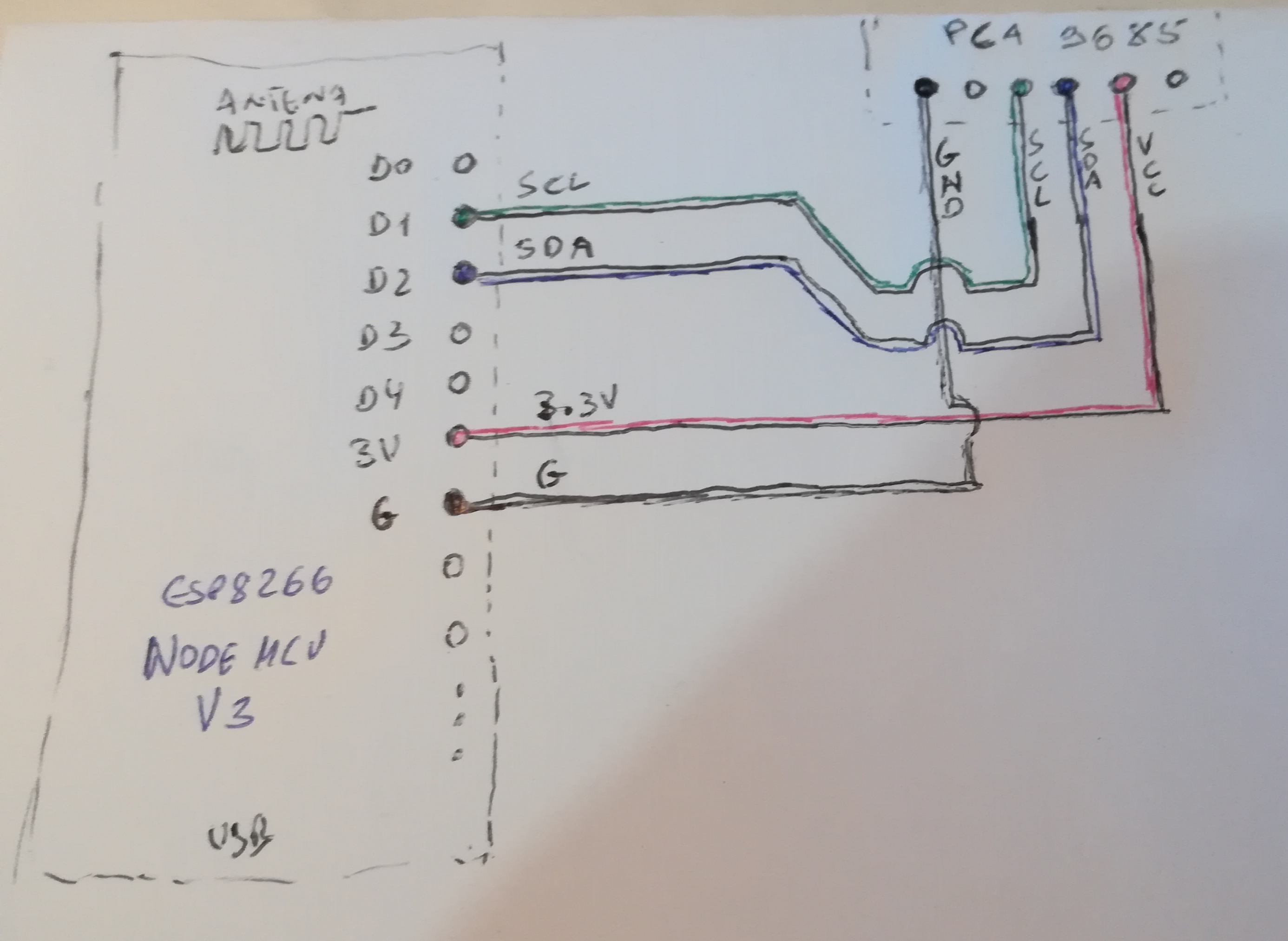
Ligações entre o ESP32 e o PCA9685

ESP32 > PCA9685

Ligações entre o PCA9685 com o servo da direcção e o esc

canal 0 – servo da direção

cana 1 – esc

multibot_description

ROS multi robot in Rviz and Gazebo demo

https://github.com/inaciose/multibot_description


roslaunch multibot_description world_1bot.launch

roslaunch multibot_description spawn_bot.launch ns:=sibot2 botcolor:=Blue x:=2

roslaunch multibot_description spawn_bot.launch ns:=sibot3 botcolor:=Red x:=3

roslaunch multibot_description world_2bot.launch